1Suspension models {#wheeled_suspension} 2======================================= 3 4 5\tableofcontents 6 7A suspension subsystem is a model of one axle of a wheeld vehicle. The base class [ChSuspension](@ref chrono::vehicle::ChSuspension) imposes that any derived suspension class (a suspension template) provide two wheel spindles (left and right) each connected through a revolute joint to some part of that type of suspension, and two spindle axles (elements of [ChShaft](@ref chrono::ChShaft) type) which may be connected to a vehicle driveline if that axle is driven. 8 9A derived suspension type defines the bodies, joints, force elements, and topology of a particular type of suspension. All locations are assumed to be provided with respect to a suspension reference frame (a derived suspension type is free to pick the location of this frame but not its orientation, which is assumed to be parallel to the chassis ISO reference frame). 10 11A suspension assembly is attached to a vehicle's chassis by specifying the location of the suspension assembly reference frame with respect to the chassis reference frame (see the definition of the [ISO reference frame](@ref vehicle_ISO_frame)). 12 13## Double wishbone {#wheeled_suspension_ChDoubleWishbone} 14 15Independent steerable suspension using two wishbone control arms (also know as A-arms) to connect the knuckle and chassis. Used as both front and rear suspension on the [HMMWV](@ref chrono::vehicle::hmmwv::HMMWV) vehicle model. 16 17See [ChDoubleWishbone](@ref chrono::vehicle::ChDoubleWishbone) and [DoubleWishbone](@ref chrono::vehicle::DoubleWishbone). 18 19<img src="http://www.projectchrono.org/assets/manual/vehicle/wheeled/DoubleWishbone_bodies.png" width="600" /> 20 21The topology of this suspension template is: 22 23<img src="http://www.projectchrono.org/assets/manual/vehicle/wheeled/DoubleWishbone_topology.png" width="800" /> 24 25The hardpoints (defined for the left side only and mirrored to construct the right side) are: 26 27<img src="http://www.projectchrono.org/assets/manual/vehicle/wheeled/DoubleWishbone_points.png" width="600" /> 28 29 30 31## Double wishbone (simplified) {#wheeled_suspension_ChDoubleWishboneReduced} 32 33This simplified double-wishbone suspension template models the lower and upper control arms using two distance constraints for each. This suspension type is suitable when the mass and inertia of the control arms are small relative to the other bodies in the system and can therefore be neglected. 34 35See [ChDoubleWishboneReduced](@ref chrono::vehicle::ChDoubleWishboneReduced) and [DoubleWishboneReduced](@ref chrono::vehicle::DoubleWishboneReduced). 36 37<img src="http://www.projectchrono.org/assets/manual/vehicle/wheeled/DoubleWishboneReduced_bodies.png" width="600" /> 38 39The topology of this suspension template is: 40 41<img src="http://www.projectchrono.org/assets/manual/vehicle/wheeled/DoubleWishboneReduced_topology.png" width="800" /> 42 43The hardpoints (defined for the left side only and mirrored to construct the right side) are: 44 45<img src="http://www.projectchrono.org/assets/manual/vehicle/wheeled/DoubleWishboneReduced_points.png" width="600" /> 46 47 48 49## MacPherson strut {#wheeled_suspension_ChMacPhersonStrut} 50 51Steerable independent suspension system which is preferred for small to mid-sized passenger cars with front wheel drive and traverse mounted engine/gearbox. 52 53See [ChMacPhersonStrut](@ref chrono::vehicle::ChMacPhersonStrut) and [MacPhersonStrut](@ref chrono::vehicle::MacPhersonStrut). 54 55<img src="http://www.projectchrono.org/assets/manual/vehicle/wheeled/MacPhersonStrut_bodies.png" width="600" /> 56 57The topology of this suspension template is: 58 59<img src="http://www.projectchrono.org/assets/manual/vehicle/wheeled/MacPhersonStrut_topology.png" width="800" /> 60 61The hardpoints (defined for the left side only and mirrored to construct the right side) are: 62 63<img src="http://www.projectchrono.org/assets/manual/vehicle/wheeled/MacPhersonStrut_points.png" width="600" /> 64 65 66 67## Multi-link {#wheeled_suspension_ChMultiLink} 68 69This suspension system is similar to a double wishbone axle. The trailing arm can bear high longitudinal forces. 70 71See [ChMultiLink](@ref chrono::vehicle::ChMultiLink) and [MultiLink](@ref chrono::vehicle::MultiLink). 72 73<img src="http://www.projectchrono.org/assets/manual/vehicle/wheeled/MultiLink_bodies.png" width="600" /> 74 75The topology of this suspension template is: 76 77<img src="http://www.projectchrono.org/assets/manual/vehicle/wheeled/MultiLink_topology.png" width="800" /> 78 79The hardpoints (defined for the left side only and mirrored to construct the right side) are: 80 81<img src="http://www.projectchrono.org/assets/manual/vehicle/wheeled/MultiLink_points.png" width="600" /> 82 83 84 85## Semi-trailing arm {#wheeled_suspension_ChSemiTrailingArm} 86 87Simple independent axle system used in smaller passenger cars as rear suspension. 88 89See [ChSemiTrailingArm](@ref chrono::vehicle::ChSemiTrailingArm) and [SemiTrailingArm](@ref chrono::vehicle::SemiTrailingArm). 90 91<img src="http://www.projectchrono.org/assets/manual/vehicle/wheeled/SemiTrailingArm_bodies.png" width="600" /> 92 93The topology of this suspension template is: 94 95<img src="http://www.projectchrono.org/assets/manual/vehicle/wheeled/SemiTrailingArm_topology.png" width="800" /> 96 97The hardpoints (defined for the left side only and mirrored to construct the right side) are: 98 99<img src="http://www.projectchrono.org/assets/manual/vehicle/wheeled/SemiTrailingArm_points.png" width="600" /> 100 101 102 103## Solid axle {#wheeled_suspension_ChSolidAxle} 104 105A solid axle system guided by four links. It normally uses coilsprings or airsprings and could be found in older passenger cars. 106 107See [ChSolidAxle](@ref chrono::vehicle::ChSolidAxle) and [SolidAxle](@ref chrono::vehicle::SolidAxle). 108 109<img src="http://www.projectchrono.org/assets/manual/vehicle/wheeled/SolidAxle_bodies.png" width="600" /> 110 111The topology of this suspension template is: 112 113<img src="http://www.projectchrono.org/assets/manual/vehicle/wheeled/SolidAxle_topology.png" width="800" /> 114 115The hardpoints (defined for the left side only and mirrored to construct the right side) are: 116 117<img src="http://www.projectchrono.org/assets/manual/vehicle/wheeled/SolidAxle_points.png" width="600" /> 118 119 120 121## Solid three-link axle {#wheeled_suspension_ChSolidThreeLinkAxle} 122 123Used as rear suspensions on the [MAN 5t](@ref chrono::vehicle::man::MAN_5t), [MAN 7t](@ref chrono::vehicle::man::MAN_7t), and [MAN 10t](@ref chrono::vehicle::man::MAN_10t) truck models. This suspension allows very high wheel travel, which could not be realized with leafsprings. It is also in on-road trucks with airsprings. Airsprings and coilsprings need a suspension guided by links. 124 125See [ChSolidThreeLinkAxle](@ref chrono::vehicle::ChSolidThreeLinkAxle) and [SolidThreeLinkAxle](@ref chrono::vehicle::SolidThreeLinkAxle). 126 127<img src="http://www.projectchrono.org/assets/manual/vehicle/wheeled/SolidThreeLinkAxle_bodies.png" width="600" /> 128 129The topology of this suspension template is: 130 131<img src="http://www.projectchrono.org/assets/manual/vehicle/wheeled/SolidThreeLinkAxle_topology.png" width="800" /> 132 133The hardpoints (defined for the left side only and mirrored to construct the right side) are: 134 135<img src="http://www.projectchrono.org/assets/manual/vehicle/wheeled/SolidThreeLinkAxle_points.png" width="600" /> 136 137 138 139## Solid three-link axle with bellcrank {#wheeled_suspension_ChSolidBellcrankThreeLinkAxle} 140 141Used as front suspensions on the [MAN 5t](@ref chrono::vehicle::man::MAN_5t), [MAN 7t](@ref chrono::vehicle::man::MAN_7t), and [MAN 10t](@ref chrono::vehicle::man::MAN_10t) truck models. 142 143See [ChSolidBellcrankThreeLinkAxle](@ref chrono::vehicle::ChSolidBellcrankThreeLinkAxle) and [SolidBellcrankThreeLinkAxle](@ref chrono::vehicle::SolidBellcrankThreeLinkAxle). 144 145<img src="http://www.projectchrono.org/assets/manual/vehicle/wheeled/SolidBellcrankThreeLinkAxle_bodies.png" width="600" /> 146 147The topology of this suspension template is: 148 149<img src="http://www.projectchrono.org/assets/manual/vehicle/wheeled/SolidBellcrankThreeLinkAxle_topology.png" width="800" /> 150 151The hardpoints (defined for the left side only and mirrored to construct the right side) are: 152 153<img src="http://www.projectchrono.org/assets/manual/vehicle/wheeled/SolidBellcrankThreeLinkAxle_points.png" width="600" /> 154 155 156 157## Leaf-spring solid axle {#wheeled_suspension_ChLeafspringAxle} 158 159Used as rear suspension on the [UAZ](@ref chrono::vehicle::uaz::UAZBUS) vehicle models. Leafspring axles have complex guiding behavior. This is a work-a-like solution, where the guiding effect of the leafsprings is simulated by a special joint in the center of the axle tube. The suspension effect is modeled by coil springs. The rolling behavior is close to a real leafspring axle. 160 161See [ChLeafspringAxle](@ref chrono::vehicle::ChLeafspringAxle) and [LeafspringAxle](@ref chrono::vehicle::LeafspringAxle). 162 163<img src="http://www.projectchrono.org/assets/manual/vehicle/wheeled/LeafspringAxle_bodies.png" width="600" /> 164 165The topology of this suspension template is: 166 167<img src="http://www.projectchrono.org/assets/manual/vehicle/wheeled/LeafspringAxle_topology.png" width="800" /> 168 169The hardpoints (defined for the left side only and mirrored to construct the right side) are: 170 171<img src="http://www.projectchrono.org/assets/manual/vehicle/wheeled/LeafspringAxle_points.png" width="600" /> 172 173 174 175## Leaf-spring solid axle with toebar {#wheeled_suspension_ChToeBarLeafspringAxle} 176 177Used as front suspension on the [UAZ](@ref chrono::vehicle::uaz::UAZBUS) vehicle models. 178 179See [ChToeBarLeafspringAxle](@ref chrono::vehicle::ChToeBarLeafspringAxle) and [ToeBarLeafspringAxle](@ref chrono::vehicle::ToeBarLeafspringAxle). 180 181<img src="http://www.projectchrono.org/assets/manual/vehicle/wheeled/ToeBarLeafspringAxle_bodies.png" width="600" /> 182 183The topology of this suspension template is: 184 185<img src="http://www.projectchrono.org/assets/manual/vehicle/wheeled/ToeBarLeafspringAxle_topology.png" width="800" /> 186 187The hardpoints (defined for the left side only and mirrored to construct the right side) are: 188 189<img src="http://www.projectchrono.org/assets/manual/vehicle/wheeled/ToeBarLeafspringAxle_points.png" width="600" /> 190 191 192 193## SAE Leaf-spring solid axle {#wheeled_suspension_ChSAELeafspringAxle} 194 195The SAE Spring Design Handbook shows a way to model a leaf spring with realistic deformation behavior under load conditions. The kinematics of a leaf spring can be defined by 5 points. These points can be used to define a leaf spring consisting of 6 rigid bodies (front leaf, front clamp, rear clamp, rear leaf and shackle). The bodies are connected by joints. The rotational springs of the front and rear leaf as well as the front clamp and rear clamp have a rotational stiffness that can be set by the user to define the correct behavior. This suspension is used as a rear suspension on the [UAZ](@ref chrono::vehicle::uaz::UAZBUS) vehicle SAE type models. The movement of the axle body due to wheel travel and the tie-up effect due to longitudinal forces can be simulated correctly with this leaf spring model. 196 197See [ChSAELeafspringAxle](@ref chrono::vehicle::ChLeafspringAxle) and [SAELeafspringAxle](@ref chrono::vehicle::LeafspringAxle). 198 199<img src="http://www.projectchrono.org/assets/manual/vehicle/wheeled/SAELeafspringAxle_bodies.png" width="600" /> 200 201The topology of this suspension template is: 202 203<img src="http://www.projectchrono.org/assets/manual/vehicle/wheeled/SAELeafspringAxle_topology.png" width="800" /> 204 205The hardpoints (defined for the left side only and mirrored to construct the right side) are: 206 207<img src="http://www.projectchrono.org/assets/manual/vehicle/wheeled/SAELeafspringAxle_points.png" width="600" /> 208 209 210 211## SAE Leaf-spring solid axle with toebar {#wheeled_suspension_ChSAEToeBarLeafspringAxle} 212 213Used as front suspension on the [UAZ](@ref chrono::vehicle::uaz::UAZBUS) SAE type vehicle models. The leaf spring definition is the same as in the SAE leaf spring axle. 214 215See [ChSAEToeBarLeafspringAxle](@ref chrono::vehicle::ChToeBarLeafspringAxle) and [SAEToeBarLeafspringAxle](@ref chrono::vehicle::SAEToeBarLeafspringAxle). 216 217<img src="http://www.projectchrono.org/assets/manual/vehicle/wheeled/SAEToeBarLeafspringAxle_bodies.png" width="600" /> 218 219The topology of this suspension template is: 220 221<img src="http://www.projectchrono.org/assets/manual/vehicle/wheeled/SAEToeBarLeafspringAxle_topology.png" width="800" /> 222 223The hardpoints (defined for the left side only and mirrored to construct the right side) are: 224 225<img src="http://www.projectchrono.org/assets/manual/vehicle/wheeled/SAEToeBarLeafspringAxle_points.png" width="600" /> 226 227 228 229## Three-link Independent Rear Suspension {#wheeled_suspension_ChThreeLinkIRS} 230 231Three-link Independent Rear Suspension (IRS), as seen on the Polaris RZR vehicle. 232 233See [ChThreeLinkIRS](@ref chrono::vehicle::ChThreeLinkIRS) and [ThreeLinkIRS](@ref chrono::vehicle::ThreeLinkIRS). 234 235<img src="http://www.projectchrono.org/assets/manual/vehicle/wheeled/ThreeLinkIRS_bodies.png" width="600" /> 236 237The topology of this suspension template is: 238 239<img src="http://www.projectchrono.org/assets/manual/vehicle/wheeled/ThreeLinkIRS_topology.png" width="800" /> 240 241The hardpoints (defined for the left side only and mirrored to construct the right side) are: 242 243<img src="http://www.projectchrono.org/assets/manual/vehicle/wheeled/ThreeLinkIRS_points.png" width="600" /> 244 245 246 247 248## Rigid suspension {#wheeled_suspension_ChRigidSuspension} 249 250Trivial assembly with spindles directly attached to an axle tube pinned to the chassis. It is typical for farm tractors and combine harvesters. 251 252See [ChRigidSuspension](@ref chrono::vehicle::ChRigidSuspension) and [RigidSuspension](@ref chrono::vehicle::RigidSuspension). 253 254<img src="http://www.projectchrono.org/assets/manual/vehicle/wheeled/RigidSuspension_bodies.png" width="600" /> 255 256The topology of this suspension template is: 257 258<img src="http://www.projectchrono.org/assets/manual/vehicle/wheeled/RigidSuspension_topology.png" width="800" /> 259 260The hardpoints (defined for the left side only and mirrored to construct the right side) are: 261 262<img src="http://www.projectchrono.org/assets/manual/vehicle/wheeled/RigidSuspension_points.png" width="600" /> 263 264 265 266## Rigid pinned-axle {#wheeled_suspension_ChRigidPinnedAxle} 267 268Trivial assembly with spindles directly attached to the axle tube that can swing around a pivot point against the chassis. This can be used, if an unsprung axle system is needed but has to run on ondulated terrain to avoid wheel lift off. 269 270See [ChRigidPinnedAxle](@ref chrono::vehicle::ChRigidPinnedAxle) and [RigidPinnedAxle](@ref chrono::vehicle::RigidPinnedAxle). 271 272<img src="http://www.projectchrono.org/assets/manual/vehicle/wheeled/RigidPinnedAxle_bodies.png" width="600" /> 273 274The topology of this suspension template is: 275 276<img src="http://www.projectchrono.org/assets/manual/vehicle/wheeled/RigidPinnedAxle_topology.png" width="800" /> 277 278The hardpoints (defined for the left side only and mirrored to construct the right side) are: 279 280<img src="http://www.projectchrono.org/assets/manual/vehicle/wheeled/RigidPinnedAxle_points.png" width="600" /> 281
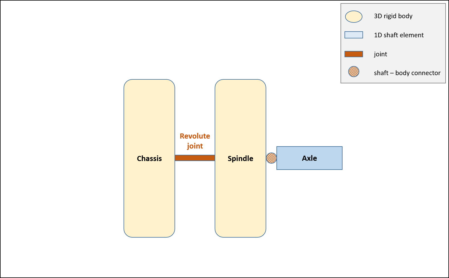
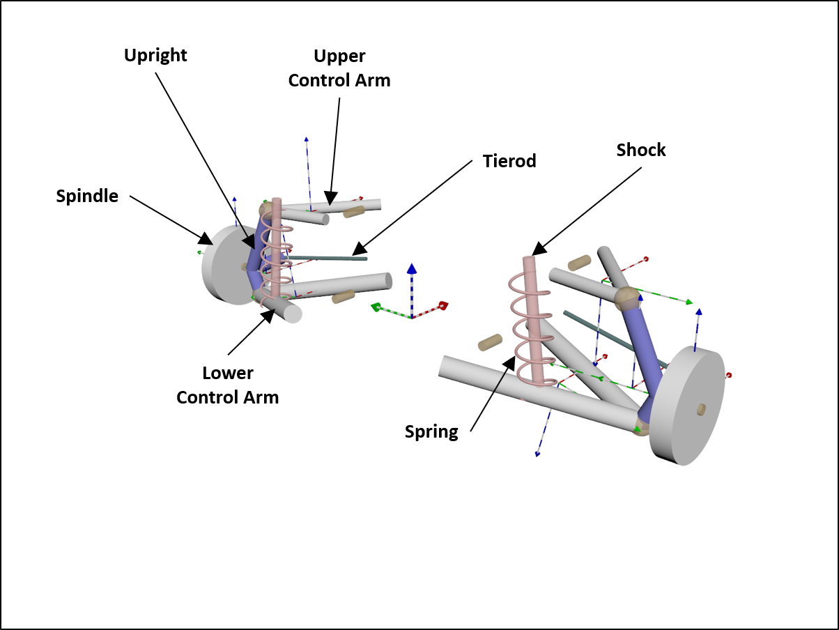
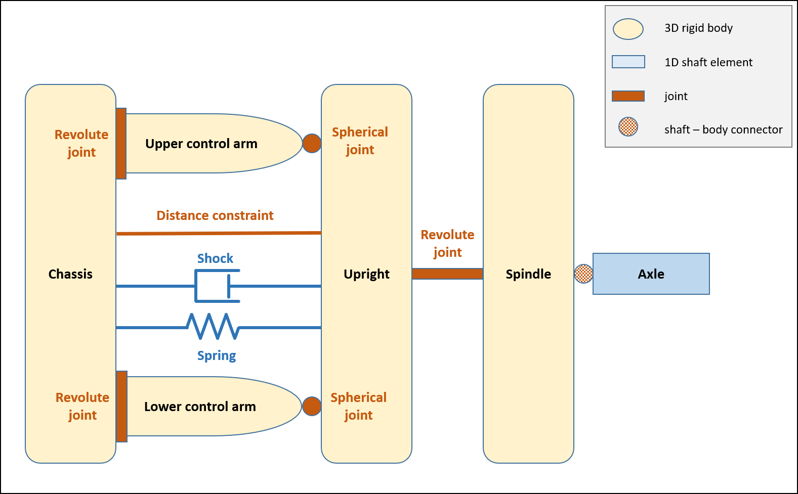
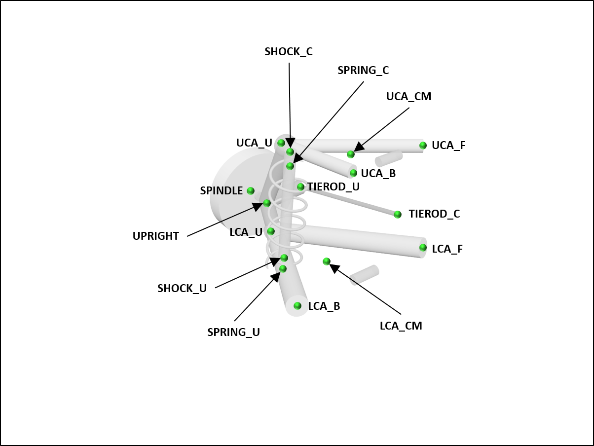
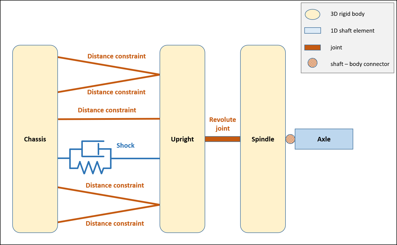
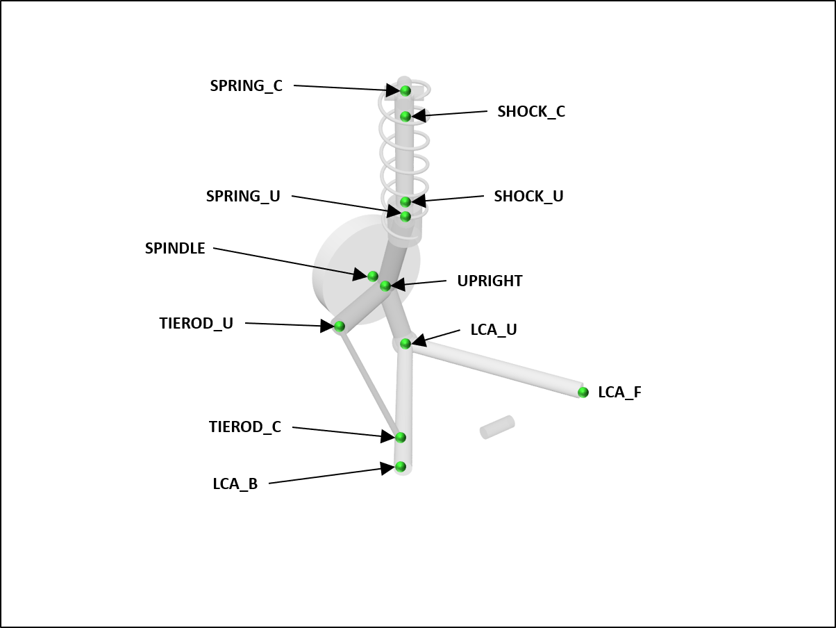